Mass Flow Technology
Introduction
Mass Flow and Mass Flow Measurement Basics
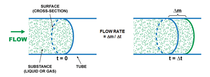
The terms mass flow or mass transfer refer to the movement of a liquid or gaseous material in a conducting element such as a tube or channel. Examples of liquid mass flow include natural phenomena such as the movement of water through a river channel and technological processes such as the passage of oil through a pipeline. Mass flow is formally defined as the "amount of substance" (determined as mass, moles, or volume) which passes through a cross section of the conducting channel during a set amount of time. Figure 1 shows how the basic parameters of mass flow are defined. The figure on the left shows material flowing through a pipe as it reaches the surface that is defined by a cross- section of the pipe at time, t=0. The figure on the right shows the pipe at time, t=Δt, when a mass of material, Δm, has passed through this surface. The flow rate is then defined as the mass per unit time that has passed through the cross-sectional surface of the pipe. It is reported as mass/time, moles/time, volume/time, etc.
The measurement of flow rates is important in many aspects of day-to-day life, ranging from determining the cost of household utilities (the measurement of water and/or gas used in a home), through transportation (how much gasoline is pumped into a car) to medical treatment (regulating a patient's oxygen flow). Flow rate measurements are even more important in industrial settings where they are critical control parameters that are used in the chemical, pharmaceutical, food and beverage, oil and gas, and high technology sectors (e.g., semiconductor device manufacturing). Chemical processes, especially, require accurate knowledge of the rate of addition of different reactants into either batch or continuous processes. Knowledge of this rate determines the stoichiometric ratios of reactants in the system which, in turn, determines realistic production targets and controls the reaction rate (important for throughput and to avoid run-away reactions) and the product yield (ratios of reactants determine the purity and composition of the products). While it is relatively easy to control the rate of addition of solids and liquids to a reaction using simple measurements of mass (using a scale) and volume (using volumetric containers), the rate of addition of compressible gases is more problematic. Since gas volumes are dependent on both temperature and pressure and reactions may be conducted under a wide variety of temperature and pressure conditions, raw measurements of gas flow rates must be converted to volumetric flow rates under standard conditions of temperature and pressure. These standard conditions, known as STP (Standard Temperature and Pressure), are normally 273.15K (0°C) and 0.9869 atm (100 kPa). Gas flow rates are reported as either SLPM (Standard Liters Per Minute) or SCCM (Standard Cubic Centimeters per Minute). Measurements at standard conditions can be used to convert volumetric flow determinations to molecular (mass) flow using the Ideal Gas Law:
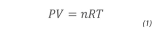
where P is gas pressure, V is gas volume, T is gas temperature, n is the number of moles of gas, and R is the gas constant. Rearranging and converting to flow over time gives an expression for the mass flow rate:

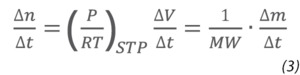
where MW is the molecular weight of the gas and Δm/Δt is the mass flow rate of the gas.
Mass Flow Meters and Controllers
Rotameters
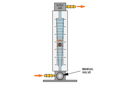
There are different ways to measure mass flow rates that are based on different physical principles. The simplest and most costeffective instrument for gas flow rate measurement is the rotameter (Figure 2). This instrument consists of a tapered tube with a float that is raised by the fluid flowing through. The height of the float in the tube varies linearly with the flow rate of the gas or liquid moving through the tube. Rotameters are ubiquitous in industrial settings owing to their simplicity, repeatability, and robust properties. They provide a rapid, visual capability for setting and monitoring gas flow, are compatible with both gases and liquids, and require no external power for operation. A low pressure drop across the rotameter ensures that the measurement produces little impact on process characteristics. The primary constraints on their use lie in the fact that they must be mounted vertically and they cannot generate an electrical signal that can be used in electronic control systems.
Thermal Mass Flow Meters
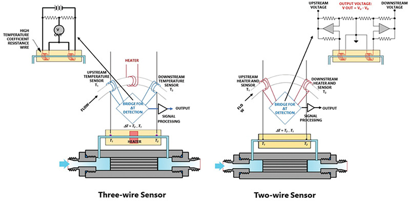
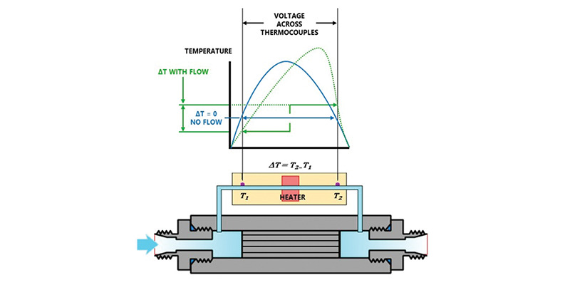
Unlike rotameters, thermal mass flow meters (MFMs) and controllers (MFCs) generate an electronic signal that can be used in process automation schemes. For this reason, they can be found in many industrial and most high technology environments that require precise process control. MFMs and MFCs employ thermodynamic principles to derive mass flow rates. Figure 3 illustrates the underlying measurement principle that is used by a thermal mass flow meter. The sensor is mounted on a side stream that takes a known ratio of the gas flow passing through the MFM. In a three-wire sensor configuration, the MFM uses high temperature coefficient of resistance wires as sensors to measure the temperature differential (ΔT=T2-T1), across a heater mounted on the side stream as shown in Figure 4. This temperature differential is directly proportional to the mass flow rate, obeying the relationship:
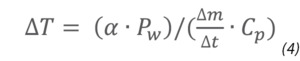
where Pw is the heater power setting, Cp is the heat capacity of the gas, a is a proportionality constant and Δm/Δt is the mass flow rate. In the three-wire sensor, a resistor bridge generates an output voltage proportional to the temperature differential, ΔT, and Equation (4) and the known splitting ratio between total flow and sidestream flow are used to determine the mass flow. A two wire sensor MFM, which is a more common configuration, employs high temperature coefficient of resistance wires as both sensor and heater, as shown on the right in Figure 4. In this configuration, circuitry adjusts the power to the heater coils to maintain a constant temperature differential between the two coils. As with the three-wire MFM, Equation (4) and the splitting ratio are used to determine the mass flow through the instrument.
Thermal Mass Flow Controllers
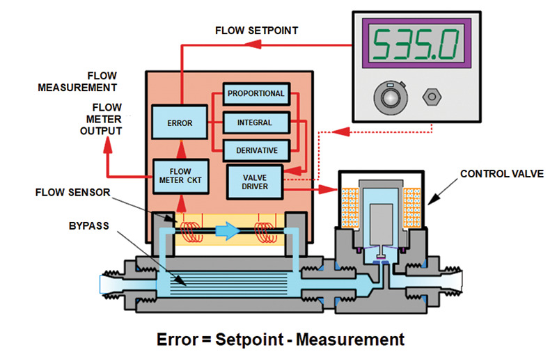
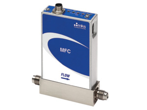
A mass flow controller (MFC, Figure 5) is a single instrument that combines both mass flow sensing and control of gas flow. It consists of a mass flow meter (MFM), a feedback controller, and a control valve. Typically, MFCs are encountered more frequently than MFMs in process environments.
Thermal MFCs are used for industrial flow control over a very wide range, with controllers available for flows between 0.01 sccm and 1000 SLPM. Thermal MFCs are both accurate and repeatable, precisely controlling gas flows between 2 and 100% of their Full Scale reading with a resolution of 0.1%. They are factory-calibrated to provide accurate and repeatable control of a specified range (Figure 6).
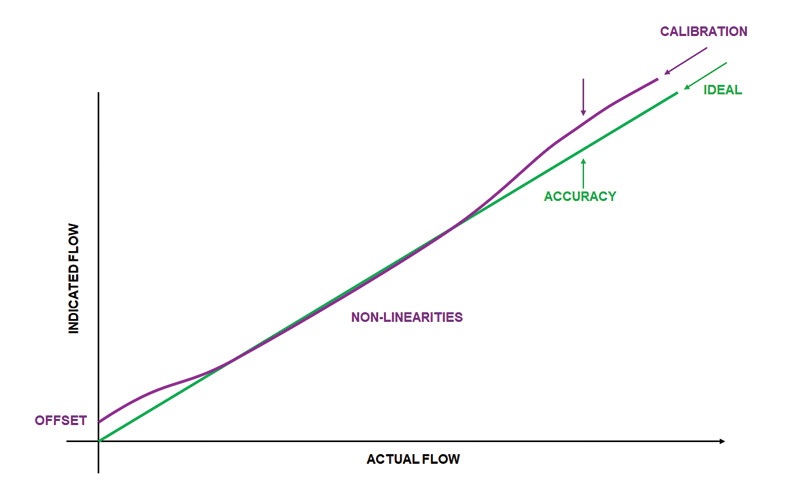
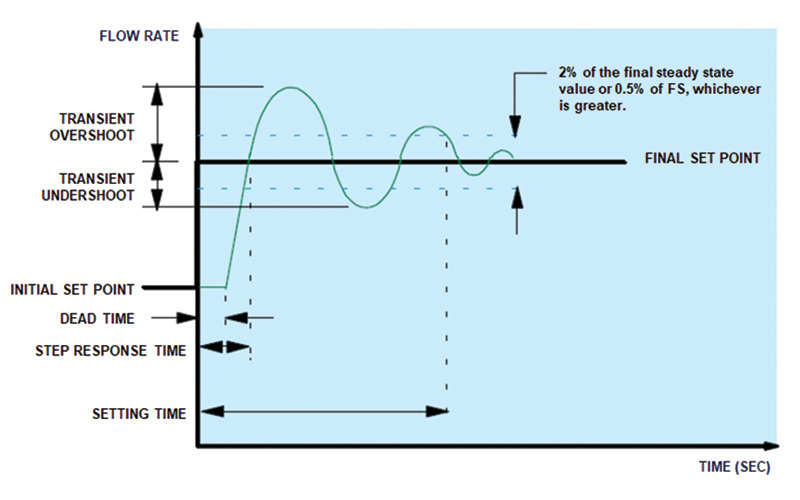
It is important to understand the different characteristics and sensitivities of thermal MFCs in order to ensure their accuracy and repeatability during operation (Figure 7).
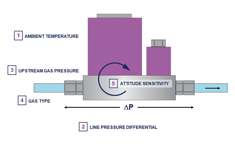
Gas type is an obvious characteristic of a given MFC calibration since the measurement of gas flow depends on the thermo-physical properties of the gas being measured. Factory calibration of an MFC is normally performed using high purity nitrogen gas after which a gas correction factor (GCF) or a multi-gas correction function is applied that adjusts the calibration for different gas types.
Gas type is an obvious characteristic of a given MFC calibration since the measurement of gas flow depends on the thermo-physical properties of the gas being measured. Factory calibration of an MFC is normally performed using high purity nitrogen gas after which a gas correction factor (GCF) or a multi-gas correction function is applied that adjusts the calibration for different gas types
.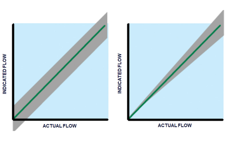
Ambient temperature will impact both the zero offset and the accuracy of mass flow measurement over the measurement span when using thermal MFCs. Figure 8 shows the impact of temperature variations on the indicated vs. actual flow in a thermal MFC. Two correction factors are associated with measurement variations due to ambient temperature. The Zero Offset Coefficient, Tc, is associated with the indicated zero in the MFC. A change in ambient temperature will shift the entire calibration curve of the MFC as shown on the left of Figure 8. The magnitude of the shift is typically of the order of ppm of Full Scale per °C. Changes in ambient temperature also shift the slope of the calibration curve over the measurement span of a thermal MFC. The Span Tc associated with an MFC exhibits behavior as shown on the right of Figure 8. The entire slope of the calibration curve is shifted, with the effect having a magnitude on the order of ppm of the reading per °C.
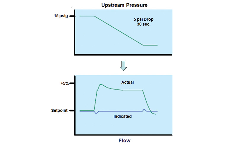
While thermal MFCs are not normally affected by downstream pressure (unless the sensor is located downstream from the control valve), changes in upstream pressure can result in variations between actual and indicated flows, as shown in Figure 9.
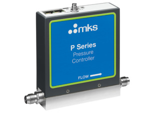
By integrating a pressure sensor into a thermal MFC, the effect of upstream pressure pertubance on MFC's accuracy can be greatly reduced. Hence, MKS provides a pressure insensitive MFC integrated with a pressure sensor such as the P9 MFC. Probably the most important, and sometimes neglected, effect on thermal MFCs is the impact that mounting attitude has on measurement and control of gas flow. Mounting attitude can impact the output of the sensors in an MFC through effects that occur either outside or inside the gas flow path (see Figure 10).
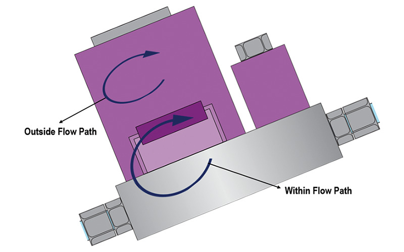
Electronics within the casing of the MFC generate heat and thermal convection currents that can transfer heat to the sensor causing errors in the gas flow readings. Within the gas flow path, some sensor/bypass designs can result in siphoning (convective flow) through the sensor when the MFC is improperly positioned. Siphoning is influenced by both gas type and line pressure and the effect can impact both the zero and span of the MFC. Typical performance characteristics for thermal MFCs are shown in Table 1 and Figure 11.
| Performance Characteristics | |
|---|---|
| Accuracy (non-linear, hysteresis, non-repeatable) | ±1% of Full Scale |
| Control Range | 2.0 to 100% of Full Scale |
| Controller Setting Time | <2 seconds (to within 2% of set point) |
| Full Scale Ranges (nitrogen equivalent) | Various, from 10 to 30,000 sccm |
| Maximum Inlet Pressure | 150 psig |
| Operational Pressure Differential | <5,000 sccm: 10 to 40 psid 10,000 to 30,000 sccm: 15 to 40 psid |
| Pressure Coefficient | 0.02% of reading per psi |
| Repeatability | ±0.2% of Full Scale |
| Resolution | 0.1% of Full Scale |
| Temperature Coefficients | Zero: <0.04% of Full Scale per °C (400 ppm) Span: <0.08% of Full Scale per °C (800 ppm) |
| Warm-up Time | 5 minutes |
Pressure-based Mass Flow Controllers
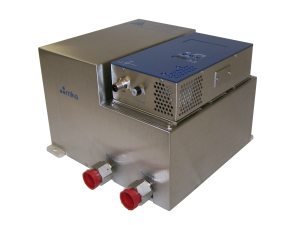
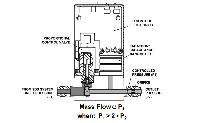
Pressure-based Mass Flow Controllers (PMFCs) were originally designed to deliver gas over a wide range of sub-atmospheric pressures, thereby maximizing the amount of gas extractable from the gas cylinders in the Safe Delivery Systems (SDS) used in the semiconductor industry (Figure 12). PMFCs thus improve source utilization and enhance safety by reducing the frequency of source bottle changes for dangerous toxic and corrosive gases. In a PMFC, a pressure transducer monitors the pressure upstream of a critical orifice – this pressure is proportional to the gas flow. The measured pressure is compared in the control electronics to the flow set point and a control signal is generated to drive the proportional control valve to the conductance required to bring the actual control pressure (flow) into agreement with the flow set point.
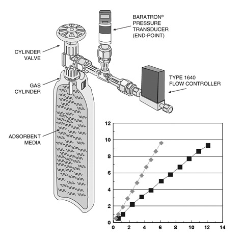
PMFCs are used in combination with Baratron® absolute pressure transducers for low line pressure applications, such as ion implant, where thermal mass flow controllers are limited in their ability to accurately measure flow. SDS units are typically low flow systems (1–20 sccm) that have sub-atmospheric inlet pressures in the range of 5 to 15 Torr. Pressure drop across a PMFC is low; typically a drop of less than 10 Torr is preferred for SDS applications. Figure 13 shows the internal configuration of an MKS Type 1640 PMFC. An orifice of known conductance is placed downstream of the pressure sensor and control valve. The pressure on the upstream side of the orifice (P1) is monitored using a Baratron absolute pressure transducer and controlled with a proportional control valve as shown. When the condition P1>2xP2 is met, the flow through the PMFC is directly proportional to P1. Table 2 provides a comparison of PMFCs with thermal MFCs.
| Parameter | MKS 1640 PMFC | Thermal MFC |
|---|---|---|
| Full Scale pressure drop (minimum) | 6 Torr | 10 Torr |
| Heat added to gas | No | Yes |
| Zero flow indication | No | Yes |
| Zero pressure indication | Yes | No |
| Direct SDS pressure indication | Yes | No |
| Indirect SDS pressure indication (valve voltage) | Yes | Yes |
| Flow independent of MFC inlet pressure | Yes | No |
| Flow independent of downstream pressure | P1>2P2 | No |
Applications
Vacuum/Pressure Control
Since process pressure is a dynamic equilibrium between gas flow into a process chamber and gas flow out of the chamber, the gas flow into a chamber can be used to control the pressure (Figure 14).
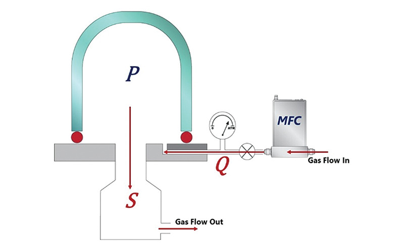
Pressure in the process chamber obeys the relationship:

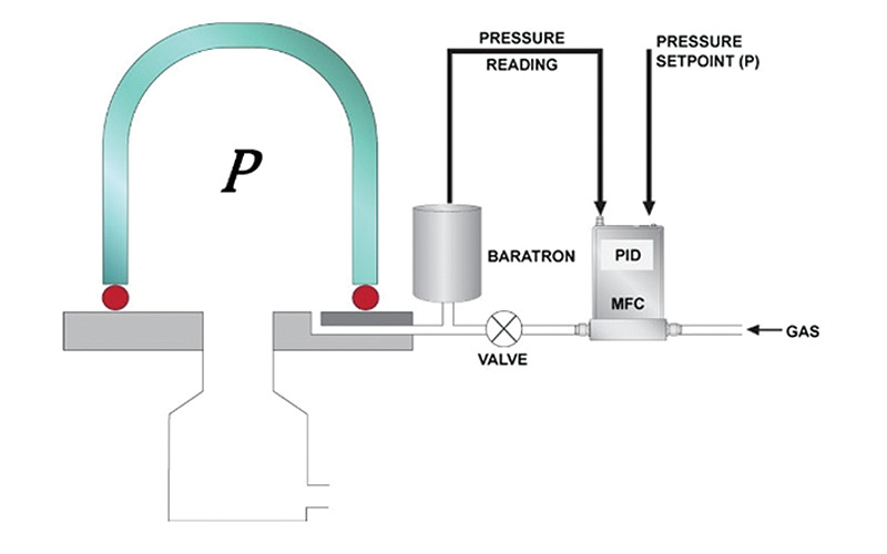
Where P is the gas pressure in the chamber, Q is the gas load, the molecular flow rate of gas into the chamber. It is controlled by the MFC. S is the pumping speed of the vacuum system which determines the molecular flow rate of gas out of the chamber. Closed-loop pressure control in a process chamber can be established by using a Baratron pressure gauge and an MFC as shown in Figure 15.
Physical Deposition
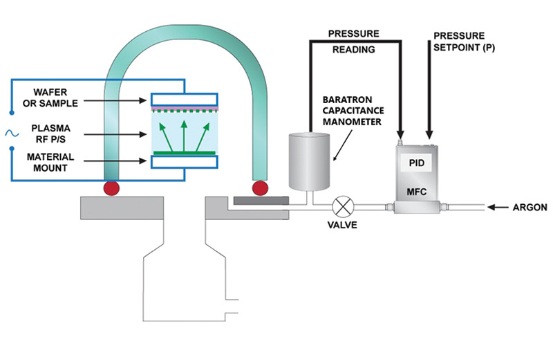
Gas pressure and composition are critical parameters that determine plasma ignition and deposition control in physical depostion process equipment such as the sputter deposition tool shown in Figure 16. In a typical sputter process, the flow rate of an inert gas such as Argon must be accurately and repeatably controlled throughout the process and process-to-process. Argon flow to a sputter deposition process chamber can be precisely and repeatably controlled using a closed-loop pressure control scheme as shown in the Figure 16.
Chemical Vapor Deposition
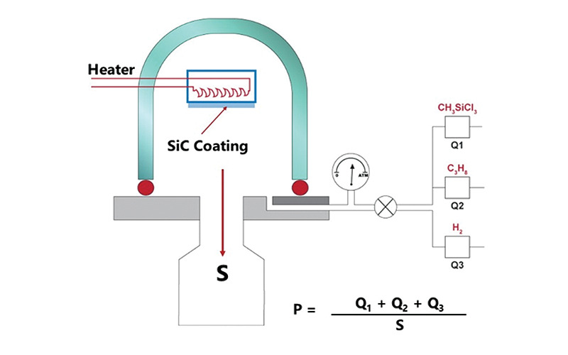
In chemical vapor deposition (CVD) processes, the flow rates of multiple precursor gases into the process chamber must be precisely and repeatably controlled. The concentration and ratio of these precursor gases in the process chamber determine both the process characteristics (e.g. deposition rate and throughput) and the material properties of the thin films produced (e.g. chemical composition, mechanical properties such as stress and finish, and film thickness). In a typical CVD tool, the flow rate of each precursor gases must be individually measured and controlled using MFCs. The cumulative flow of the different precursor gases is additive in determining the total molecular gas flow into the chamber and the chamber pressure is determined by the relationship shown in Figure 17.
Broad Selection for Varied Industries
MKS Instruments is a global leader in MFC technology and supplies a variety of different MFC types to industries such as semiconductor fabricators, display manufacturers, and photovoltaic cell manufacturers. MKS' line of thermal MFCs include the fast and repeatable G-Series thermal MFCs that provide a cost-effective flow control solution for most industrial and technological applications. G-Series MFCs are available as either elastomer or metal-sealed units with flow ranges up to 300 SLPM. They are available with a wide choice of digital (RS485, Profibus™, EtherCAT®, Profinet or DeviceNet™) or analog (0–5 VDC or 4–20 mA) I/O options. MKS IP66-rated thermal MFCs are designed specifically for applications that have harsh environments where protection against water and dust is critical. IP66-rated mass flow controllers have IP66-rated enclosures that are dust tight and protect against powerful water jets. They offer digital (Profibus®) or analog (0–5 VDC or 4–20 mA) I/O. MKS' P-Series thermal MFCs are high performance multi-gas, multi-range mass flow controllers that are designed for critical applications where accuracy, repeatability, and pressure insensitivity are required. They have gas parameters stored in memory that allow user selected gas measurement and control with 1% set point accuracy. As with other MKS thermal mass flow controllers, P-Series MFCs have analog (0–5 VDC) or digital (DeviceNet, RS485) I/Os. The C-series is a compact MFC using a Micro-Electro-Mechanical Systems (MEMS) based flow sensor designed for non-corrosive gas applications. The C-series MFC is available with analog (0–5 VDC) or digital (RS485, Modbus TCP/IP) I/Os.
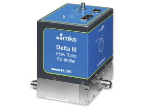
MKS Instruments also supplies pressure based flow controllers (such as the metal-sealed 1640A MFC) and a number of specialized mass flow control solutions such as flow ratio controllers (Delta II, III, and IV Mass Flow Ratio Controllers for up to 4-zone ratio control), Mass Flow Verifiers and single- and dual-zone pressure controllers (G-series and P-series integrated pressure controllers and DPC Dual-Zone Pressure Controllers).