
Vapor Sublimation Process Traps
Vapor Sublimation Process Traps
Vapor sublimation traps are widely used in silicon nitride LPCVD and Titanium nitride LPCVD processes where significant amount of NH4Cl byproducts have been observed in the foreline. The Vapor Sublimation Trap draws in effluent vapors and solidifies them before they have a chance to backstream to the reaction chamber, contaminating and hazing your wafers. It also prevents gases from entering and damaging your vacuum pump.
- Improved wafer yields
- Increased uptime
- Protects vacuum pump
- Low cost of ownership
- Ease of maintenance See All Features
Configuration Options
Vapor Sublimation Process Traps are available with the following options.
|
Configuration Option |
Option Code |
|---|---|
| Vapor Sublimation Process Trap | WCTRAP |
| Port Size | |
| NW50 | 050 |
| NW80 | 080 |
| NW100 | 100 |
| Configuration | |
| Angle (NW50 & NW100) | A |
| Heatable Angle (NW80 only) | H |
| Inline (NW80 & NW100) | N |
| Flange | |
| ISO-KF (NW50 only) | K |
| ISO-MF (NW80 and NW100 only) | M |
| Body Size | |
| 6 inch | 6 |
| 8 inch | 8 |
| Seal Type | |
| Viton® | V |
| Silicone | S |
| Water Fittings | |
| Straight | QRS |
| Elbow | QRL |
| 3/8 in. Tube | None |

Specifications
- Capacity6 inch: 3.0 lbs (1.4 kg) NH4C
8 inch:10.0 lbs (4.5 kg) NH4CI - Flow Conductancep = pressure in mTorr
6 inch: C (I/sec) = 20.74p
8 inch:C (I/sec) = 45.63p - Pressure DropQ = gas flow rate in sccm
p = pressure in mTorr
6 inch: Dp (mTorr) = 812 Q/p2
8 inch: Dp (mTorr) = 369 Q/p2 - Dry Weight6 inch: 16.5 lbs (7.5 kg)
8 inch: 28.0 lbs (12.7 kg)
- Cooling Water Temperature< 86° F (30° C)
- Cooling Water Flow Rate> 6 gal/hr (400 ml/min)
- Efficiency> 99%
Features
Improved Wafer Yields
In processes used at several major semiconductor fabs we have seen 2-3% improvement in overall yields. There are three reasons for this:
- The high flow conductance of the trap leads to a lower base pressure in the furnace. With a lower base pressure, less residual gas remains in the furnace. This prevents redeposition of the gas on the wafer, causing hazing.
- The lower base pressure leads to a lower vapor pressure for the gas. This reduces particles backflowing to the furnace
- The large transition zone in the trap reduces clogging. A change in pressure occurs when the trap is about 70-80% full. This will indicate the need to clean the trap, preventing clogging in the middle of a wafer process run.
Increased Uptime
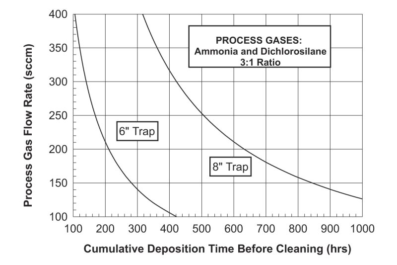
In nitride process systems it is common to see a five time increase in intervals between cleaning. The trap has a patented thermal transition zone, which allows for optimized cooling of the gas so that the solidifiable vapor does not all collect in the port area of the trap. The MKS 6 inch Vapor Sublimation Trap was designed to be cleaned in a nitride process with a gas flow rate of 150 sccm, every 250-280 runs. The 8 inch high-capacity trap with the same gas flow, will last 750-850 hours. Actual run hours may be different depending on gas ratios. The figure shows an estimate of the cumulative deposition time before cleaning.
Protects the Vacuum Pump
Solids are very damaging to vacuum pumps. Even if the by-product enters the pump as a vapor, compressing it will convert the vapor to a solid. The trap has a patented two stage design (see Figure). Close to 95% of the gas is collected in the first stage. The second stage contains perforated cones that collect the remaining 5% to achieve over 99% collection efficiency and maintain high flow conductance of the trap. This prevents the ammonium chloride from clogging or damaging the pump, and reduces the amount of dilute gas required for purging the pump.
Low Cost of Ownership
The use of the 6” trap by two major semiconductor fabs allowed them to increase their maintenance cycle from 26 runs to over 120 runs. This resulted in 5-8 extra runs per week or an increased uptime of 16 hours per week. If the profit generated per machine is $1,000 to $5,000 per hour, a savings of $16,000 to $80,000 per week is realized. A trap costs around $2,000, so the payback for this investment is less than one day.
Ease of Maintenance
For cleaning NH4Cl, fully immerse the trap in a circulating water bath for about one hour. When the trap is clean, dry it in an oven. This removes all the water, which could contaminate the system when the trap is reinstalled.
Water leaks, during trap removal for cleaning, are essentially eliminated with the self-sealing, quick release coupling option. These couplings for the cooling water inlet and outlet ports ease installation and removal by eliminating the need to shut off the water source.
Vapor Sublimation Trap Operation
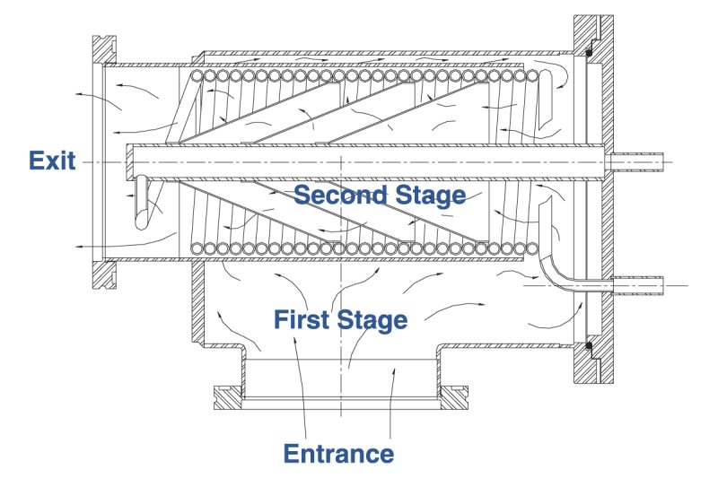
Vapor Sublimation Trap accomplishes collection of solidifiable vapor in two stages. The first stage, at the entrance of the trap, has a high capacity to trap more than 95 percent of all condensable gases. The figure is a cross section of the Vapor Sublimation Trap. It shows the high volume reserved for first stage trapping. This avoids rapid clogging frequently encountered with other traps. In just half the volume, the trap has the capacity to capture more than five times the vapor than the nearest competitor.
The second stage is a polishing scrubber designed for greater efficiency. This stage maximizes heat transfer between the gas and the cooling surface, while maintaining high flow conductance. The combination of cooling water coils and perforated stainless steel cones solidifies the residual vapors that have passed through the first stage.
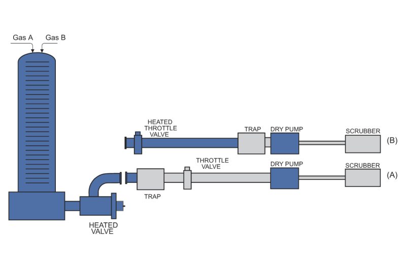
Maximizing Trap Efficiency
Heated lines and valves upstream of the Vapor Sublimation Trap maximize the benefits and efficiency of the trap and should be used to ensure reduced particulate contamination. With the combination of the two contamination reduction methods, the total number of process runs significantly increases before any cleaning is necessary. The figure shows how many hours of deposition time can be attained based on gas flow rates of typical silicon nitride LPCVD systems.
Vapor Sublimation Trap Applications
Semiconductor CVD processes produce gaseous by-products that can readily be pumped out of the reaction chamber. However, they usually solidify in a vacuum pipe line since the line temperature is lower than the reaction chamber. A clogged line means longer down time and lower product yield, especially with the trend of larger wafers and smaller feature size.
One of the most common processes is LPCVD silicon nitride. Since sublimation is temperature driven, use heat to maintain the by-products in the vapor phase and use cooling to intentionally sublimate the vapors in the trap.
LPCVD Nitride
LPCVD silicon nitride process deposits solid silicon nitride on the wafer and creates an ammonium chloride (NH4 Cl) by-product. Ammonium chloride will solidify in the vacuum pump line if the line is not heated. To keep NH4 Cl in its vapor stage, the system temperature must be from 130°C to 150°C at 150 mTorr. This allows the system to transport it away from the furnace. Higher pressures will require a higher temperature (see the vapor pressure curve in the figure).
In a typical silicon nitride CVD process the NH3 /DCS ratio is around 3 to 1. A higher NH3 /DCS ratio leads to longer cumulative deposition time. There are several reasons for installing heated lines and a Vapor Sublimation Trap in a silicon nitride CVD process.
- Collecting NH4 Cl in the trap for ease of maintenance;
- Large trapping capacity leads to longer preventative maintenance cycles for increased uptime;
- High trapping efficiency provides better protection of the pump, control valve and downstream instrumentation;
- Lower NH4 Cl vapor pressure in the trap (due to lower temperature) results in higher process yield.
Other Semiconductor Processes
The Vapor Sublimation Trap can be used in other semiconductor processes where by-product vapors can be physically solidified and cleaned by dissolving them in a solution (like water). For example, ammonium hexaflurosilicate (NH4)2SiF6 has been observed in a silicon nitride PECVD process due to the cross chemical reaction between the by-products formed in the deposition process and the etching process.
Accessories
| Compare | Description | Drawings, CAD & Specs | Avail. | Price | ||
|---|---|---|---|---|---|---|
 | 100003597Bonnet Flange Seals, Viton, for 6 in. Vapor Sub Trap | |||||
| 100004790Bonnet Flange Seals, Silicone, for 6 in. Vapor Sub Trap | 3 Weeks | ||||
| 100004954Replacement Internals, for 6 in. Vapor Sub Trap | 5 Weeks | ||||
| 43PWRCORD04Power Cord, 6 ft., Ground Fault Circuit, Vapor Sublimation Trap Heaters | 4 Weeks | ||||
| 100004980Water Fittings, Straight, Self-Sealing, Quick Release | |||||
| 100009608Replacement Internals, for 8 in. Vapor Sub Trap | 6 Weeks | ||||
| 100004981Water Fittings, 90 Elbow, Self-Sealing, Quick Release | |||||
 | 100762020Viton O-Ring, NW200 Size ISO-MF Vacuum Flange, 2-371 O-Ring Size | 7 Weeks | ||||
| 100009637Bonnet Flange Seals, Silicone, for 8 in. Vapor Sub Trap | 2 Weeks | ||||
| 9635-1091Heater, Vapor Sublimation Trap, Inline, 8 in. body, NW80 Port, 120 VAC | |||||
| 9640-0273Heater, Vapor Sublimation Trap, Angle, 6 or 8 in., NW80, Temperature Alert | |||||
| 9635-1094Heater, Vapor Sublimation Trap, Inline, 6 in., NW80, Low Temperature Alert | |||||
| 9635-1093Heater, Vapor Sublimation Trap, Inline, 6 in. body, NW80 Port, 120 VAC | |||||
| 9640-0291Heater, Vapor Sublimation Trap, Angle Body, 6 or 8 in., NW80 Port | |||||
| 9635-1092Heater, Vapor Sublimation Trap, Inline, 8 in., NW80, Low Temperature Alert | |||||
| 9640-1091Heater, Vapor Sublimation Trap, Inline, 8 in. body, NW100 Port, 120 VAC | |||||
| 9640-1092Heater, Vapor Sublimation Trap, Inline, 8 in., NW100, Low Temperature Alert | |||||
| 9640-1094Heater, Vapor Sublimation Trap, Inline, 6 in., NW100, Low Temperature Alert |
Resources
Literature
Vapor Sublimation Trap Datasheet(413.7 kB, PDF)
Manuals
Vapor Sublimation Trap Operation and Maintenance Manual(170.2 kB, PDF)
