
PDPCA Dual-zone Pressure Controllers with Mass Flow Meter
PDPCA Dual-zone Pressure Controllers with Mass Flow Meter
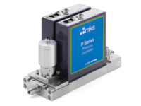
The P-Series Dual-Zone Pressure Controller (PDPCA) is a highly integrated closed-loop pressure control subsystem. It consists of an inlet pneumatic shut-off valve, two independent channels of pressure control with mass flow metering, and a vacuum outlet. The pressure control channels consist of two P-Series pressure controllers (PPCMA). Each PPCMA provides both pressure control and flow metering.
- Available with EtherCAT® or DeviceNet™ communications
- Less plumbing and cabling required
- Pressure measurement accuracy of ±0.5% of set point See All Features
Configuration Options
The following options are available for PDPCA Dual-Zone Pressure Controllers
Ordering Code Example: PDPCA51T12810
| Configuration Option | Option Code |
|---|---|
|
PDPCA Dual-Zone Pressure Controller with MFM |
PDPCA |
Pressure Range Full Scale |
|
| 20 Torr | 21T |
| 50 Torr | 51T |
| 100 Torr | 12T |
Full Scale Flow Rate |
|
| 20 sccm | 21C |
| 50 sccm | 51C |
| 100 sccm | 12C |
Unit Configuration |
|
| EtherCAT | 8 |
| DeviceNet | 6 |
Firmware Revision |
|
| EtherCAT Version | 10 |
| DeviceNet Version | 10 |
Gas and Bleed Flow Rate |
(Consult Applications Engineering) |
Specifications
- TypeDual Pressure Controller
- Pressure Range20, 50, or 100 Torr, Full Scale
- Fitting TypeSwagelok® 4 VCR® male compatible
- Pressure Control Accuracy±1.0% set point1
- Transducer Over Pressure Limit45 psia or 200% Full Scale, whichever is greater
- Pressure Measurement Accuracy±0.5% Reading
- Zero Temperature CoefficientPressure: <0.02% Full Scale/°C
Flow: <0.05% Full Scale/°C - Span Temperature CoefficientPressure: <0.04% Reading/°C
Flow: <0.08% Reading/°C - Control Range10-100% Full Scale
- Typical Response Time<2.0 seconds to set point, typical - dependent on system configuration and control settings
- Operating Temperature15-50°C (59-122°F)
- Storage Temperature-20 to 80°C (-4 to 176°F)
- Storage Humidity0-95% Relative Humidity, non-condensing
- External Leak Integrity<10-9 scc/sec He
- Leak Integrity Through Closed Valve<1% Full Scale
- Flow Measurement Range20, 50 or 100 sccm, Full Scale
- Maximum Inlet Pressure45 psia
- Flow Accuracy±1.0% Full Scale
- Wetted Materials316L Stainless Steel, Inconel®, Nickel, Elgiloy®, Viton®
- Surface FinishRa <10 µinches, electropolished
- Input PowerEtherCAT: +24 VDC (<5 watts)
DeviceNet: +11 to 25 VDC (<4 watts), each channel - ConnectorEtherCAT: 2 x RJ-45 (comm.) male, M8 male, 5 pin (power)
DeviceNet: M8, 5 pin micro connector (Power and Communications), each channel - Data Rate SwitchEtherCAT: No switch
DeviceNet: 4 positions: 125, 250, 500K (Default), Programmable over network. - EtherCAT Communication Rate100 Mbps
- DeviceNet Communication RateN/A
- MAC ID SwitchesEtherCAT: 3 switches, 16 positions
DeviceNet: 2 switches, 10 positions: 0,0 to 6,3. 1 to 254 - Network SizeEtherCAT: Up to 4095 nodes
DeviceNet: Up to 64 nodes - IndicatorsEtherCAT: Up to 4095 nodes
DeviceNet: LED Network (green/red); LED Module (green/red) - Meter Warm-up Time1 hour
- Stability at set point<0.1% set point
- Weight10.5 lbs. (4.8 Kg)
- Dimensions10.46 (incl. fittings) x 3.36 x 5.35 in.
26.56 (incl. fittings) x 8.53 x 13.59 cm
Features
- Complete backside wafer cooling subsystem in a compact package
- Two independent channels of pressure control, each with mass flow metering
- With single package integration, size and complexity are reduced greatly
- Can be used in any application requiring independent pressure control and mass flow metering to two distinct volumes
- Tunable response for fast time to set point without pressure overshoot
- Control stability of ±0.1% of set point
PDPCA Operation
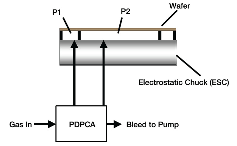
The PDPCA has been designed to reduce the overall cost of ownership of pressure control subsystems for backside wafer cooling, specifically for the latest two-zone electrostatic chucks (Figure 1).
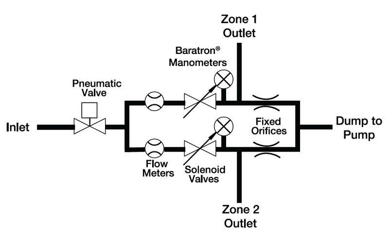
As shown in Figure 2, the PDPCA consists of four sections – an inlet subassembly, two PPCMA pressure control channels and an outlet subassembly. Pressurized helium gas is provided in the inlet subassembly. A pneumatic valve is then opened and the gas flow is split to two pressure control channels.
In the pressure control section, the PPCMA utilize MKS Baratron® capacitance manometers to measure pressure for each of the two zones. These pressures are compared to the pressure set points and an appropriate signal adjusts the position of the solenoid control valve to bring actual pressures into agreement with the set points. At the same time, mass flow is monitored on each channel by MKS mass flow meters calibrated for helium, which is the typical gas used for backside wafer cooling.
Downstream of the pressure control section, the outlet subassembly directs flow to the electrostatic chuck and provides a controlled "bleed" to vacuum through fixed orifices.
The purpose of the bleed is to insure that the pressure control system is not "dead-ended". Since leak past the wafer is typically very low, the controlled bleed provides additional pressure relief for faster response to set point.
The controlled bleed is done using a fixed orifice based sccm of helium at a 9 Torr set point.
Resources
Literature
PDPCA P-Series Dual-Zone EtherCAT® Pressure Controller(2 MB, PDF) PDPCA P-Series Dual-Zone DeviceNet Pressure Controller(2.1 MB, PDF)
Manuals
PDPCA Dual Zone Pressure Controller Manual(1.1 MB, PDF) PDPCA Dual Zone Pressure Controller EtherCAT Supplement(584.5 kB, PDF) PDPCA Dual Zone Pressure Controller DeviceNet Supplement(750.3 kB, PDF)
Drawings & CADs
PDPCA 4VCR EtherCAT STEP File(4.2 MB, ZIP) PDPCA EtherCAT Dimensional Drawing(454.7 kB, PDF)
Device Description Files
PDPCA EtherCAT ESI File(242.4 kB, XML)