Vacuum Pressure Control for Semiconductor Fabrication
Stable and precise control of a processing system's vacuum pressure is critical for high-yield semiconductor device fabrication. Processes such as SAPCVD, LPCVD and etch exhibit optimal behavior at well-defined process pressures and it is critical to maintain and transition process pressures in a well-controlled, stable manner. Similarly, advanced processes such as ALD must have tight control over system pressures during gas switching steps. The required vacuum pressure control in these and other semiconductor unit processes is accomplished using closed-loop control for a number of variables that affect the vacuum process.
To understand the issues involved in vacuum/pressure control in semiconductor process equipment, consider the simplified schematic for a hypothetical process control system in a deposition or etch tool as depicted in Figure 1 (for the sake of simplicity, plasma processing is not considered). The Figure shows the equipment components with connections denoting the primary inputs and outputs used by an automatic process controller for the different control functions in the system. The process controller in this particular instance requires vacuum pressure information from the different vacuum gauges depicted in Figure 1 as input for automated gas switching, purge/reactant gas flow control, wafer transfer, and vacuum/pressure control.
Vacuum/pressure gauges provide key information that is used to trigger different actions in a process sequence. Consider the following (much simplified) process recipe steps for a hypothetical deposition process performed in the process tool shown in Figure 1.
- Load substrate in loadlock and seal loadlock
- Pump down loadlock to rough pump base pressure
- Equalize loadlock and process chamber pressures
- Transfer substrate to process chamber and seal chamber
- Purge process chamber and pump to mechanical pump base pressure
- Open valve to high vacuum pump and bring process chamber to high vacuum base pressure
- Isolate high vacuum pump
- Open isolation valve to mechanical pump
- Establish purge gas flow at expected process pressure
- Bring chamber and process to process temperature setpoint under purge gas flow
- Switch from purge gas to process gas
- Run deposition process for pre-set time
- Shut off process gas and pump to rough pump base pressure
- Cycle purge process chamber to remove residual process gas
- Pump chamber to rough pump base and equalize loadlock and chamber pressure
- Transfer substrate to loadlock and seal process chamber
- Isolate loadlock and backfill to 1 atm with purge gas
- Remove finished substrate
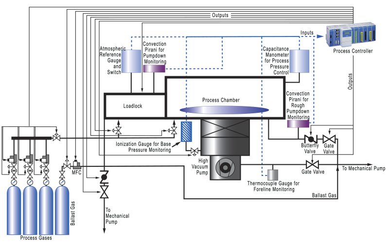
It is easy to see that there are many times in this process sequence when the process controller needs information on the pressure in either the loadlock or the process chamber in order to perform a process step. The simple task of loading the substrate into the loadlock requires that the pressure in the loadlock be equal to or greater than that in the surrounding fab environment, otherwise atmospheric pressure would prevent the outer loadlock door from opening. A differential pressure gauge comparing the loadlock and atmospheric pressures can tell the controller if the pressures are equal. If not, the controller can add additional purge gas to bring the pressures into equilibrium. Once equilibrium is established, a simple switch can release the loadlock door and allow substrate loading.
Since overall control of the process is not our focus in this section, we will only give further consideration to steps in which vacuum/pressure control is needed. Step 2 in the process above requires that the loadlock be pumped from atmospheric pressure down to the base pressure of the rough pumping system which is typically around 10-3 Torr. If the process simply opened a valve between the loadlock and the mechanical pump, the loadlock would quickly pump down to base pressure. However, the pneumatic shock and accompanying turbulence would disturb any particles in the loadlock, contaminating the substrate surface. This is avoided by adjusting the pumping speed on the loadlock from relatively low at the beginning of the pumpdown to full speed once the loadlock pressure is close to base pressure. Once the system is under vacuum, pneumatic shocks during purge and process gas switching are normally avoided through the use of precise and controlled adjustments of the gas flow rates. Steps 9 and 10 in the process sequence also require vacuum pressure control. In these steps, the gas flow and pumping speed must be adjusted to maintain an optimal pressure during the deposition process. While there is some relationship between gas flow and process pressure, the optimal process pressure does not usually occur at the optimal gas flow values and these two variables must be controlled separately.
Semiconductor processing systems commonly use one of three main approaches to vacuum/pressure control in process steps such as those discussed above:
- Control the pumping speed by changing rotational speed of a mechanical blower
- Control the pumping speed by adjusting the flow rate of ballast gas feed between the process chamber and pump
- Control the pumping speed by adjusting the vacuum conductance of the vacuum downstream foreline using a throttling valve
| Blower Speed Control | Ballast Gas Control | Downstream Control | |
|---|---|---|---|
| Dynamic Range | Low - 10:1 Typical | Moderate - 500:1 typical, 1000:1 max | High - 1000:1 typical, 10,000:1 max |
| Types of Pumps | Will not work with all pumps | Works with any pump that can operate at process pressure | All |
| Speed of Response | Moderate | Fast | Fast |
| Initial Capital Cost | AC or SCR motor controller | Bypass valve and optional controller | Exhaust valve and controller |
| Extra Operating Costs | None | None | None |
| Susceptibility to Effluent Gases | None | None | Slight |
| Special Requirements | Pump controller and flow rates must be properly sized | Pump controller and flow rates must be properly sized | None |
Table 1. Pressure control techniques.
Automatic closed-loop control of the vacuum/pressure is accomplished by monitoring the process pressure using, most commonly, a capacitance manometer which provides a feedback signal for chamber pressure to a process control system. This system uses PID (Proportional Integral Derivative), a common combination of control algorithms or some other kind of control algorithm to generate corrections to the pressure control setpoints in one of the control schemes detailed above (1 to 3 above). Table 1 compares the different approaches to vacuum/pressure control over a number of operational and cost parameters.
Vacuum/Pressure Control Application Products
MKS's approach to vacuum pressure control focuses on the equipment needed for vacuum isolation and downstream closed-loop control of each variable that affects a vacuum process (subsequent sections).
In the downstream control approach, an exhaust throttle valve is opened or closed, changing the conductance to the vacuum pump in order to achieve and maintain the desired process pressure this separates the process variables of gas flow and process pressure, making them independent of one another within the limits of acceptable process conditions. Downstream pressure control provides high dynamic range, works well with all types of vacuum pumps, has a fast response time, is tolerant to most effluent gases, and has moderate initial costs.
MKS's product line for vacuum pressure control allows the user to isolate and maintain closed-loop control of the process pressure through the use of a throttling control valve and digital PID or self-tuning pressure controllers. A typical pressure control system that uses MKS components works as follows:
- A Baratron capacitance manometer senses pressure in a vacuum chamber
- This pressure is compared to the desired set point pressure in the pressure controller
- The pressure controller commands the control valve to open or close, changing the chamber pressure and bringing it to the desired process set point
The following products enable this approach to vacuum/pressure control. MKS supplies detailed product configurations for reliable pressure management and downstream pressure control.
Vacuum Isolation Valves
Integral to any vacuum/pressure control scheme is the ability to isolate a process system from the vacuum source (pump). MKS produces a broad spectrum of application-specific vacuum isolation valves. The MKS family of valves includes: bellows sealed valves, ball valves, soft start dual-stage valves, UHV valves, and safety shut off valves. Valve actuation includes manual, pneumatic, and electromagnetic actuators. They are extremely reliable with lifetimes of up to 1,000,000 cycles under clean conditions. Specialty valves for harsh process conditions include heated valves that prevent by-product condensation and deposition, and corrosion resistant valves for applications such as metal etch.
Downstream Valves and Pressure Controllers
MKS supplies downstream throttling control valves in a number of configurations, both as stand-alone units with integrated controllers and as units configured for remote control. Many downstream pressure control valves are available in heated options.
Stand-alone units include T3Bi high speed valves, and "smart" exhaust throttle valves such as the 153D and 683B valves. T3Bi valves are high speed throttling valves that integrate all control, communication, and driver circuits within the throttle valve assembly, eliminating the need for a separate pressure control electronics module. The T3Bi self-tuning control algorithm and high-speed operation drives the system to set point quickly and with minimum overshoot, ensuring repeatability in process recipes. RoHS compliant, the T3Bi valve accepts Baratron manometer inputs and accommodates multiple communications protocols for ease of integration into local control schemes. T3Bi valves are programmable for pressure, position or set point limits. T3Bi valves are particularly well suited for "house exhaust" or atmospheric pressure throttling applications. The 153D and 683B valves are based on the standard 253B exhaust throttle valve with add-on electronics that eliminate the need for separate control modules. The 153D and 683B valves can be configured for either pressure control or flapper position control. They exhibit linear valve transfer characteristic for smooth, linear pressure control. They are specifically designed for computer-controlled applications where a simple pressure control system is desired.
MKS also supplies conventional throttle valve and remote controller configurations in the 253B exhaust throttle and 653B high speed exhaust throttle valve products with associated controllers such as the 651C digital/analog pressure controller. The MKS Type 253 is available in standard sizes and flange styles, and is compatible with all MKS throttle valve controllers. Type 653 valves are available in a variety of sizes and flange styles, and are compatible with MKS Type 651 and 1651 controllers.
MKS provides an excellent overview in the Downstream Pressure Controllers and Valves product selection guide.
Upstream Valves and Pressure Controllers
MKS supplies upstream gas flow control valves that can be interfaced with appropriate MKS controllers and pressure sensing valves to control chamber pressure by regulating the gas flow into the chamber. Both conventional valve/controller and fully integrated valve/controller configurations are available. Conventional upstream valve and valve controller combinations include the baseline 248D flow control valve, the 148J all-metal control valve, and the 154B high flow valve which can be controlled using the MKS 651 and 1651 pressure controllers. These valves can be controlled using the 1249 solenoid control valve driver. The control valve driver is intended for use with PCs, PLCs or other controllers that provide the necessary PID control functions but do not have the required current output to drive a flow control valve.
MKS supplies integrated upstream pressure valves and controllers for closed-loop electronic pressure control. These are self-contained compact, closed-loop electronic control systems used for upstream or downstream pressure control. MKS's 640B and 641B absolute and gauge pressure controllers contain a Baratron capacitance manometer, a normally-closed proportional control valve, and closed-loop control electronics. Pressure output and input control signals in these controllers are linear 0-5 VOC or 0-10 VDC. Two trip points are included in the 640/641, with LED status indicators, for use as simple on/off process limits. The 640 and 641 pressure controllers can be interfaced with a single- or four-channel power supply/readout.
In addition to single zone integrated pressure controllers, MKS offers the DPC dual-zone pressure controller that integrates an inlet pneumatic shut-off valve, two independent channels of pressure control with mass flow metering, and a vacuum outlet. This was designed to reduce the overall cost of ownership of pressure control subsystems for backside wafer cooling, specifically for the latest two-zone electrostatic chucks.
MKS also offers the πPC series PC90 integrated closed-loop pressure controller and PC99 integrated closed-loop pressure controller that includes a mass flow meter. The πPC pressure controller provides digital control in a web-enabled format. It is a self-contained, compact, closed-loop electronic pressure control system that is designed for a wide range of pressure and flow conditions. It contains a Baratron capacitance manometer, normally closed or normally open control valve, and closed-loop control electronics. The πPC is available in either an upstream or downstream pressure control configuration, making it well suited for controlling process chamber backpressure or process gas delivery pressure. With either digital (DeviceNet or RS-485) or analog I/O and its Ethernet setup/diagnostics capabilities, the πPC is easily integrated into most process tools. The πPC pressure controller is a complete, compact pressure control package that minimizes cost and space requirements. MKS offers several different models of vacuum/pressure switches for accurate and reliable protection of vacuum equipment, atmospheric switching, and vacuum/pressure processes. Designed for applications where a DC signal output is not required, these switches provide relay outputs that are readily interfaced with alarms, valve actuators, computers, process controllers, load locks and other protection devices.
Vacuum/Pressure Calibrators
A transfer standard is a secondary device that is traceable to a national laboratory or other recognized standards body (e.g., National Institute of Standards and Technology, NIST). Transfer standards are used in both laboratory and production environments. MKS's PVS6E vacuum calibration system provides NIST-traceable calibrations over pressures ranging from 10-5 to 1000 Torr and can be used to calibrate capacitance manometers, thermocouple gauges, Pirani gauges, convection enhanced Pirani gauges, other capacitance manometers and transmitters, and mechanical/dial gauges. Hot or cold cathode ionization gauges can be calibrated over the upper end of their range. In addition, the SRG-3 spinning rotor gauge can be used as a traceable standard for calibration of pressure measurements.
Related Topics
Front-end Semiconductor
For additional insights into semiconductor topics like this, download our free MKS Instruments Handbook: Semiconductor Devices & Process Technology
Request a Handbook