Principles of Vacuum
Introduction
What is Vacuum?
The broadest definition of vacuum is simply "an absence or near absence of matter". In practical terms, a vacuum can be created in a closed vessel by removing all or part of the air within the vessel. Vacuums are employed in many manufacturing technologies, ranging from incandescent light bulbs to thermal drink containers to food preservation. In technology, vacuum conditions are important for producing the thin film coatings that are used in applications ranging from the trivial (i.e., reflective balloon coatings) to the critical (i.e., hardened tool coatings, integrated circuit components, anti-corrosion coatings, etc.). Much of modern scientific research would not be possible without effective vacuum containment. Researchers in chemistry, physics, and high technology routinely employ vacuum to create an environment in which the physicochemical conditions are precisely known. Under vacuum conditions they can perform experiments with highly controlled levels of molecular and surface interactions and with minimal influence due to unknown contaminants. As well, the prediction of gas behavior is simplified under vacuum conditions since gases come closer to obeying the Ideal Gas Law as pressure is reduced.
The degree of vacuum within a vessel is determined by the gas pressure, defined as a measure of the cumulative force of individual gas molecules colliding with each other and with the walls of their container. The force (pressure) the gas exerts on the walls of a container is defined as Force/Area or F/A. This force is a function of the number of molecules in the container and the rate at which momentum, mass × velocity, mv, is transferred from the moving molecules to the container surface. The force per unit time exerted on the wall of a container by a single molecule can be expressed as:

where t is the time between collisions of the molecule with the wall. Using this definition for molecular force, pressure can be expressed in terms of the cumulative force exerted by all the molecules in a container:

where NV is the number of molecules in the container, m is the mass of the molecule, v its average velocity, and V the volume of the container. Since the average kinetic energy of a molecule is related to the absolute temperature by

we can re-state the Ideal Gas Law in molecular terms as:

where k is the Boltzmann constant and T the absolute temperature. Since the Ideal Gas Constant, R, is just the Boltzmann constant multiplied by Avogadro's Number (N0, the number of molecules in a mole of substance - 6.022×10²³), Equation (4) is exactly equivalent to the familiar

where n is the number of moles of gas and R is the Ideal Gas Constant. The molar volume of a gas is a constant (Avogadro's Law) with one mole of gas occupying 22.4L at STP (Standard Temperature and Pressure, 1 atmosphere pressure, 0°C). This means that the number of molecules in a liter of gas at room temperature is 2.46 x 10²². There are thus 22 decades of molecular density between atmospheric pressure and 1 molecule/liter.
This serves to illustrate the fact that it takes very high vacuum conditions before the physical and chemical effects of residual molecules are reduced. More detailed discussions of the molecular underpinnings of vacuum science and technology can be found in references [1] and [2].
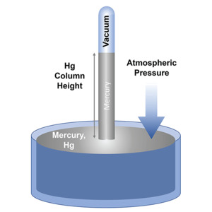
Figure 1. The mercury manometer.
Vacuum pressures are most often measured using a unit called a Torr, derived from the name of the 17th Century scientist who first measured atmospheric pressure, Evangelista Torricelli. His method of measuring air and vacuum pressures used a glass tube that was filled with mercury and then placed upside down in a dish of mercury (this type of measurement device is known as a mercury manometer, Figure 1). He found that the force of the atmosphere (atmospheric pressure has a value of 760 Torr) on the mercury in the dish would support a column of mercury in the tube that was 760 mm high. This is the reason behind the seemingly odd number of units for atmospheric pressure in this system of measurement. When the pressure on the dish of mercury was lowered (i.e., when it was placed in a vacuum environment) the height of the column of mercury was reduced an amount proportional to the drop in pressure. Vacuum and meteorological measurements in the European and Asian systems usually refer to pressures in"atmospheres" where 1 atmosphere (referred to as 1 bar) is the normal atmospheric pressure at sea level. Vacuum measurements in this system are usually reported in terms of 1/1000th's of an atmosphere (the millibar). The Pascal is the unit used for pressure measurement in the SI system. A Pascal equals 1 Newton/m2.
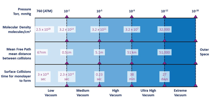
Figure 2. Vacuum pressure, classifications, and physical characteristics.
Figure 2 shows classifications for the levels of vacuum between atmospheric pressure and outer space along with three physical parameters that are important in the use and understanding of vacuum science: molecular density; mean free path; and the time required to form a monolayer of gas molecules on a clean surface. Atmospheric pressure, as noted, is 760 Torr. Molecular density is an important parameter in determining chemical reaction rates and physical properties such as evaporation rates. At atmospheric pressure, a very large number of molecules or atoms, 2.5 x 10¹⁹, are present in a cubic centimeter of gas. This large number means that the molecules in a gas at atmospheric pressure undergo frequent collisions with other molecules. The molecular density is an important parameter in determining chemical reaction rates (proportional to the frequency of collisions between molecules) and physical properties such as the rate of heat transfer through a gas. The mean free path, average distance travelled between collisions, at atmospheric pressure is only 67 x 10-9 meters (67 nm). To help put this in perspective, this means that in air at atmospheric pressure, a molecule of nitrogen can only travel a distance equivalent to 184 molecular diameters before undergoing a collision with another molecule. The mean free path in a vacuum system influences physical properties such as gas flow characteristics and ion storage and transport that are important considerations in high temperature and high energy physics research and technology. High molecular densities and low mean free paths mean that a clean surface will rapidly accumulate a monolayer of gas atoms at atmospheric pressure, an issue which impacts fundamental studies in surface science as well as practical technologies such as thin film coating techniques. For example, a perfectly clean surface will accumulate a monolayer of adsorbed gas within 3 nanoseconds at atmospheric pressure. Only under ultra-high vacuum (UHV) conditions does the experimenter have sufficient time to work with such a clean surface (it takes nearly 40 minutes to accumulate a monolayer at UHV). Figure 2 shows how these physical parameters vary with pressure. The lowest pressure that can be routinely achieved in a laboratory setting is about 10-12 – 10-13 Torr, with the record for artificial vacuum achievement being 10-14 – 10-15 Torr.
Producing a Vacuum
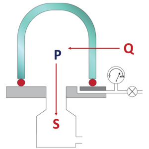
Figure 3. Equilibrium gas flows in a vacuum chamber.
In a laboratory or production environment, the pressure that can be achieved in a vacuum chamber is the result of a dynamic equilibrium between incoming and outgoing gas flows. This is shown schematically in Figure 3. The pressure in the vacuum chamber obeys the relationship:

where P is the vacuum pressure, Q is the molecular gas flow rate inward (gas load), and S is the molecular gas flow rate outward (pumping speed). Once a stable vacuum has been achieved in a chamber, the gas load, Q is due to a combination of any gas flow deliberately fed to the chamber plus any leakage into the chamber from the surrounding ambient atmosphere. Pumping speed, S, is determined by the size and type of vacuum pump employed in the system and by the gas conductance of the lines between the pump and the vacuum chamber. Many different physicochemical processes contribute gas loads to the flow within a vacuum chamber (Figure 4). Each of these constitutes an impediment to the system achieving the lowest ultimate system pressure.
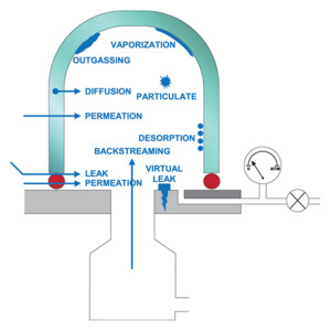
Figure 4. Contributors to the unintended gas load in a vacuum chamber.
Leaks are the most obvious contributor to unintended gas load in a vacuum system. Leaks can occur either as direct leaks, for instance through a bad O-ring seal in a joint, or as virtual leaks from trapped pockets of gas such as the dead space at the end of a bolt hole. Virtual leaks can also occur from sources such as bad welds, non-vented gasket grooves and blind stud holes. Direct leaks exhibit characteristic pressure-rise behavior during a static leak check. They are typically detected and resolved by systematically replacing the O-ring seals in different system components. Virtual leaks are more difficult to detect and manage. Therefore, vacuum systems are designed to avoid any potential for virtual leaks by using TIG welding, vented screws, and slotted surfaces. Typically, O-rings provide adequate leak protection in low to medium vacuum applications, while high, ultra-high, and extreme vacuum applications require metal knife-edge seals to ensure against leakage at joints.
Another source of unintended gas load is outgassing, i.e., the release of gas and vapor from the chamber walls, elastomer seals and other materials within the vacuum environment. Outgassing can be identified by the fact that the gas load increases with increasing temperature of the surfaces within the vacuum environment and that the rate of outgassing diminishes over time as the system continues to be pumped. Sources of outgassing include the vaporization of water adsorbed on the chamber surfaces, desorption of synthetic oils and greases (e.g., machining oil) or residual solvents from cleaning system components, and inadvertent contamination such as fingerprints on a vacuum-wetted surface. Outgassing can be resolved by baking the vacuum system at high temperatures (compatible with all system components). As well, good vacuum practices such as wearing protective gloves while handling components that will be exposed to vacuum and avoiding solvents for cleaning can help to mitigate outgassing in a vacuum system.
Other contributors identified in Figure 4 are less frequent impediments to a vacuum system achieving the lowest possible pressure. Diffusion and permeation of external gases through elastomer gaskets and O-rings or through chamber walls is only an issue in ultra-high or extreme vacuum systems. This is the reason that only metal knife-edge seals are used in high, ultra-high, and extreme vacuum conditions. Permeation of gas through chamber walls is not usually an issue unless specialty materials (e.g., helium can permeate through glass bell jars) are required in the chamber. Backstreaming, noted in Figure 4, is not usually an issue in modern dry-pumped vacuum systems, unless material has built up on the surfaces in the vacuum conductance lines and absorbed volatile species. Appropriate system hygiene can help to minimize this problem.
When all contributors to gas load are included, Equation (6) can be restated in the following form:

- Compression-expansion of the gas (piston pumps, rotary pumps, Root's (dry) pumps – to 10-3 Torr)
- Drag by viscosity effects (vapor ejector pumps – to 0.1 Torr)
- Drag by diffusion effects (vapor diffusion pumps – to ~10-9 Torr)
- Molecular drag (molecular drag or turbomolecular pumps to 10-10 Torr)
- Ionization effects (ion pumps – to 10-12 Torr)
- Physical or chemical sorption (sorption pumps, cryopumps and gettering processes – to 10-11 Torr)
Within the semiconductor industry, high-capacity vacuum pumps (S up to 10,000 l/s) that operate on the compression-expansion principle, molecular drag pumps such as turbopumps, and physical sorption pumps such as cryopumps are most frequently encountered. Oil-free dry pumps dominate semiconductor processing since they eliminate issues with backstreaming.
Another important factor that influences the ultimate pressure that can be attained in a vacuum system is the gas conductance in the system. The gas conductance between the vacuum pumping system and vacuum chamber depends on the pressure differential between the chamber and pumping system, the length and diameter of any connecting vacuum line, the conductance through control components, and the number and severity of any bends or constrictions in the pipe. Methods and tables for the calculation of vacuum line conductance are widely available (e.g., References [2] and [6]). The relationship between pumping speed and system conductance is expressed as:


Figure 5 shows the pump-down curve for a hypothetical vacuum system. Typically, any vacuum process begins with an initial pump down. Because the effective pumping speed of the vacuum system is proportional to the differential pressure across the system, the initial pumpdown is rapid. Base pressure in the system is a pressure chosen as appropriate for the process which is to be carried out. Base pressure is not the ultimate low pressure achievable in the system; the ultimate pressure of the system is usually much lower. However, it can take an exceedingly long time to achieve the ultimate system pressure so base pressure targets are chosen as a compromise between the chamber cleanliness and process gas purity requirements of the process and acceptable processing times. Base pressure is a process specification (target) while ultimate vacuum is a vacuum system specification. Typically, vacuum systems should be designed so that their ultimate pressure is at least 10x lower than the base pressure needed for the planned process. This ensures that the system can achieve base pressure rapidly, allowing the process to begin without prolonged pump-down times. Vacuum modelling software is available that can calculate the pressure distributions at a system's ultimate vacuum. This software provides critical insights for the design of modern process chambers in terms of outgassing characteristics, conductance restrictions, and pump selection.
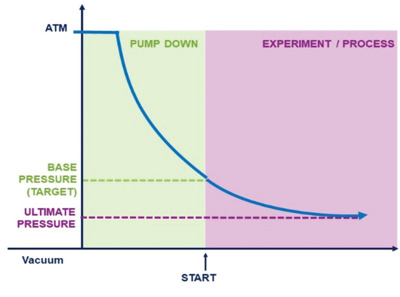
Figure 5. Hypothetical pump-down curve.
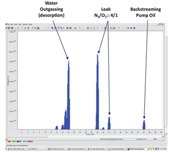
Figure 6. RGA trace showing different contaminant fingerprints.
The quality of a vacuum must be assured before any processing can occur in a vacuum system. This is accomplished by a combination of static leak checks and vacuum analyses using analytical tools such as a Residual Gas Analyzer (RGA). Static leak checks are simple procedures in which the system is first pumped down to base pressure then isolated and the rate of rise of the pressure is measured. The process specification will have a pre-defined rate of rise that is acceptable, and which must be achieved before processing can occur. Vacuum analysis by RGA is a more precise method for the determination of the quality of the vacuum within a system. RGAs are chemical analyzers, most often based on a compact quadrupole mass spectrometer, that can be attached to the system for vacuum analysis. The use of RGAs can save significant time in characterizing and trouble-shooting vacuum systems since they provide characteristic signatures that allow the user to differentiate between the different causes of pressure rise within the system. Figure 6 shows a representative RGA analytical trace for a hypothetical vacuum system. The trace shows the different type of signatures that can be observed using this method. Each peak in the trace measures the molecular mass (more accurately, mass/charge) of a chemical (ionic) species or its breakdown product that has been detected in the system. For instance, water, with a molecular mass of 18 (O + 2H) produces a signature trace with peaks at 18, 17, and 16. Similarly, air leakage into the system produces a characteristic fingerprint with peaks for molecular nitrogen (28) and oxygen (32) at a 4:1 ratio. Other contaminants such as backstreaming pump oil all produce characteristic fingerprints in an RGA trace.
Vacuum Processing
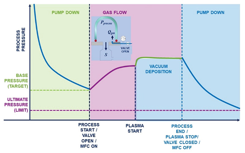
Figure 7. Hypothetical pressure characteristics of a plasma process.
Once a system has achieved base pressure and a static leak check or RGA analysis has shown that there are no issues with leakage, outgassing, backstreaming, etc., a vacuum process can start. Figure 7 shows the process pressure trace for a hypothetical plasma process. Most industrial processes (e.g., thin film deposition and etch) require a process gas flow into the chamber for purposes such as chemical reaction or gas purging. So, the process starts with the delivery of precisely controlled gas flow(s) into the chamber, usually using precision mass flow controllers that provide an accurate and controllable gas flow, Qgas. Gas flow is controlled from 0 up to the desired setpoint, producing a smooth, gradual pressure rise in the vacuum chamber until a stable flow/pressure state is achieved. Pumping speed, S, and therefore pressure in the chamber, is controlled using a control valve. Both Qgas and S are controlled in a vacuum process, along with other variables such as plasma power and substrate temperature. The vacuum process pressure obeys the relationship:
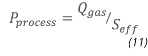
To ensure reproducible process results (i.e., chemical composition, contamination- and corrosion-free operation, etc.) gas flow, pressure, and gas composition are monitored and tightly controlled in real time throughout a vacuum process.
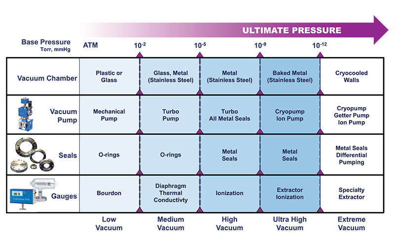
Figure 8. Materials and components for different vacuum systems.
Figure 8 shows how the materials and components required in a process vacuum system vary with the ultimate pressure achievable in the system. Vacuum chambers for a medium vacuum (between 10-2 and 10-5 Torr) system can be fabricated from glass, stainless steel or other metals while chambers for high vacuum (between 10-5 and 10-9 Torr) applications are exclusively fabricated from stainless steel. Ultra-high vacuum (between 10-9 and 10-12 Torr) chambers are typically made from stainless steel and they must be designed to allow high temperature bake-out of the entire system. Extreme vacuum systems must employ cryocooled walls. All vacuum systems typically employ a mechanical pump with medium and high vacuum applications requiring the addition of a turbopump to achieve their ultimate pressures. Ultra-high and extreme vacuum systems employ cryo-, getter, and ion pumps. While low and medium vacuum systems can employ permeable elastomer O-ring seals, only metal seals can be used for high, ultra-high, and extreme vacuum systems. Finally, different pressure gauges are required depending on the ultimate pressure. Mechanical or thermal gauges are suitable for direct pressure measurements in low and medium vacuum applications, while high, ultra-high, and extreme vacuum gauges require more complex indirect measurement gauges based on ion behavior in the vacuum.
MKS Instruments Vacuum Process Control and Analysis Instrumentation
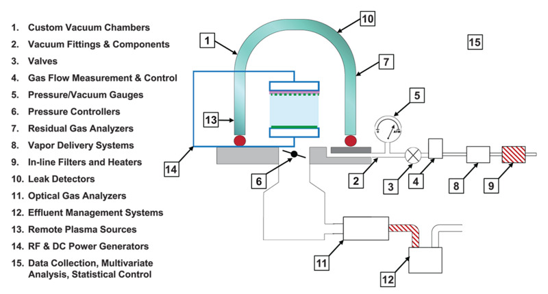
Figure 9. Process vacuum chamber showing different system components.
MKS Instruments provides a broad array of vacuum equipment, including a suite of process control and analysis instrumentation. Figure 9 shows a schematic of a vacuum chamber with the ancillary components necessary for process measurement and control. MKS supplies cutting edge solutions for each of the vacuum process containment, measurement, analysis, and process control functions detailed in the list in Figure 9.
References:
[1] A. Roth, Vacuum Technology, Third, Updated and Enlarged ed., Amsterdam: Elsevier Science B. V., 1990.
[2] J. F. O'Hanlon, A User's Guide to Vacuum Technology, Hoboken, New Jersey: John Wiley & Sons, 2003.
[3] N. S. Harris and L. Budgen, "Design and manufacture of modern mechanical vacuum pumps," Vacuum, vol. 26, no. 12, pp. 525-529, 1976.
[4] Oerlikon Leybold Vacuum, Fundamentals of Vacuum Technology, W. Umrath, Ed., Cologne, 2007.
[5] J. Hennings, "Thirty years of turbomolecular pumps, A review and recent developments," Journal of Vacuum Science and Technology A, vol. A6, p. 1196, 1988.
[6] Oerlikon Leybold Vacuum, Fundamentals of Vacuum Technology, W. Umrath, Ed., Oerlikon Leybold Vacuum, 2002.
 Ultra-High Velocity