Ionization Vacuum Gauge Physics
UHV and XHV pressure measurements are routinely performed using ionization gauges configured as either hot cathode gauges (HCGs) or cold cathode gauges (CCGs). Both sensor types determine pressure from measurements of an ion flux created by collisions between energetic electrons and residual neutral gas molecules within the gauge (see our earlier discussion). HCGs employ thermionic emission from a filament as a source of electrons while CCGs use a circulating space charge to create a free electron plasma.
When the pressure of a vacuum system is below about 10-4 Torr, direct pressure measurement methods such as capacitance manometers and Pirani gauges no longer work well and it becomes necessary to use methods that basically count the number of molecules in the gas space. This latter quantity is called the number density and is commonly given the symbol n. In terms of the number density, the pressure can then be calculated as:
p=cnT
where p is the pressure, c is a constant and T is the temperature. Ionizing the gas and collecting the ions is a convenient way of establishing the number density in the gas phase since there is a well-defined statistical relationship between the collisional dynamics that create ions and the number density of molecules in a gas and hence the pressure of that gas. Ionization gauges perform this measurement using free electrons that have been produced by either thermionic emission or plasma generation. The ion current that is collected by the negatively biased collector can be related to pressure once the gauge has been calibrated. The basic gauge equation for ionization gauges is:
IC = KnIe
where Ic is the ion current, K is a constant relating to the ionization probability, n is the number density of gas molecules and Ie is the ionizing electron current.
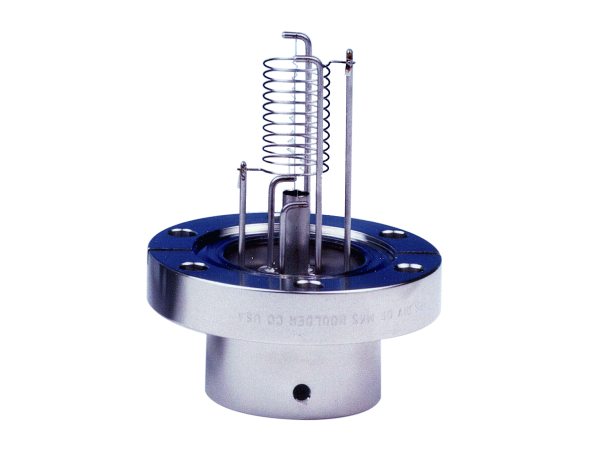
Figure 1 shows a typical Bayard-Alpert (B-A) hot cathode ionization gauge. It has three electrodes: the cathode or filament, the collector and the anode grid. Energetic electrons emitted from the cathode (biased at about 30 Vdc) are accelerated towards the anode grid (typically 180 Vdc) colliding with and ionizing molecules present in the gas phase. The positive ions that are created in the collisions are accelerated towards the collector (0 Vdc) located along the axis of the anode grid producing an ion current that is measured by the gauge electrometer. This gauge configuration produces a strict, linear relationship between collector current and pressure. HCG measurements are gas-dependent since different atoms and molecules exhibit different ionization efficiencies (due to factors such as electron-molecule collision cross-section and ionization potential). They are usually calibrated for either nitrogen or argon and attention must be paid to the relationship between the gauge calibration gas and process gas protocols when selecting a HCG. Gas correction factors are available that permit field adjustment of HCG readings.
The useful operating range of measurement of the HCG is defined, in the upper limit, by restrictions on the mean free path of the ions when the number density in the gas phase becomes too high. At high number densities, an ion has a high probability of interacting with either a free electron or a neutral molecule before reaching the collector. When this happens, the initial electron-molecule ion creation event no longer contributes to the ion current, introducing inaccuracies in the relationship between that current and the system pressure. In practical terms, this upper limit for the use of ionization gauges is about 10-3 Torr. Historically, the lower limit of HCGs was considered to be reached when either electrical leakage currents in the gauge head or the controlling electronics become comparable with the ion current being measured. However, advances in modern electronics have extended the lower limits of these gauges into the XHV regime. In HCGs, the lower limit is the so-called X-ray limit. In an HCG, X-rays are emitted when electrons impact the grid. A small fraction of these X-rays are intercepted by the ion collector in the HCG where they cause electrons to be photoelectrically ejected. This photoelectron current leaving the collector is electrically detected as identical to the positive ion current, adding to the current and producing a false pressure reading. This phenomenon results in the standard lower limit for pressure measurement using the best conventional HCGs having a value of around 10-11 Torr.
With good operating protocols and proper calibration, the sensor-to-sensor reproducibility of Bayard-Alpert HCG readings is typically about 2%. Repeatability of readings is 1-2%, limited mainly by uncontrollable random sensitivity variations.
Care must be taken to avoid exposure of the working components of an HCG to process gases while the HCG is operating (other than purge gases such as nitrogen and argon). Reactive gases can damage gauge components when they are at operating temperature, either through unwanted deposition or through corrosion. Even when the gauge is not "on", process and ambient gases will adsorb on the components of the HCG and these materials will slowly desorb from the gauge surfaces during normal operation, increasing the local pressure within the gauge. "Degassing" can be used to drive the molecules adsorbed on the gauge surfaces back into the process chamber, where they can be pumped out of the system. Degassing can be done as required or as part of a regular pumpdown sequence. Regular degassing helps prevent process deposits from collecting and ensures that the HCG provides the most sensitive and repeatable pressure indications.
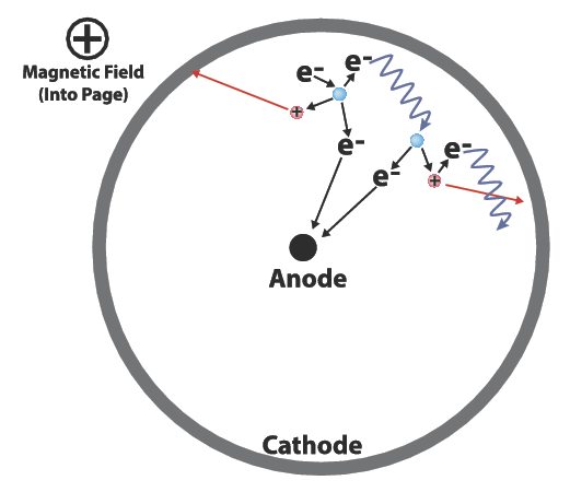
Cold cathode gauges, also known as Penning gauges (after their inventor), have been in use since the late 1930's. CCGs differ from HCGs in that they employ high voltages between the electrodes (in the kV range), in place of a hot filament, to generate free electrons and a crossed magnetic field to create a controlled electrical current path in the gauge. CCGs rely on randomly emitted electrons caused by cosmic rays, a radioactive source, and field emission to initiate stable electron plasma within the current path of the gauge. The discharge within a CCG normally ignites within a very short time at 10-6 Torr or above, a few minutes at 10-8 Torr, and longer times at lower pressures. In operation, the crossed fields trap a near-constant circulating electron current in this path. Electrons moving within the conduction path collide with residual gas molecules, producing the ion flux that is measured. Figure 2 shows a schematic that can help in understanding the ion generation mechanism within CCGs. In the Figure, Electron 1 (whose path begins on the left side of the circle) is accelerated by the electric field in approximately cycloidal jumps around the anode at a constant radius until it encounters a neutral molecule. If it has sufficient energy, the electron causes an ionization event which produces a positive ion and an additional electron (2) which undergoes acceleration in the conduction path in a manner similar to electron 1. The ion generated in the collision moves to the cathode where its impact generates a secondary electron which similarly enters into the conduction path. Through these mechanisms, the circulating electron current quickly builds to a stable value, determined by the fields and geometry within the sensor. Once a critical electron density is reached, space charge depression of the electric field within the device prevents any further production of electrons from the cathode. The circulating electron current becomes very stable and nearly independent of pressure and surface conditions.
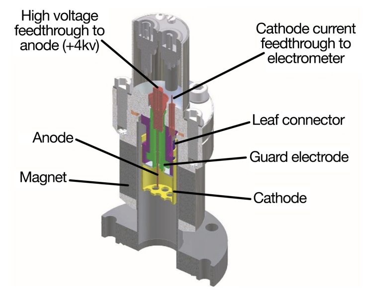
Since its invention, the cold cathode gauge has undergone numerous evolutionary developments that have extended its range and accuracy. The inverted magnetron sensor geometry is now the most commonly used for CCGs, owing to its wide range and freedom from spurious effects. The advent of inverted magnetron designs enabled the development of compact CCGs capable of measurement below 10-10 Torr. Other improvements, such as isolation of the collector and the use of guard electrodes have further broadened the spectrum of application for CCGs. Today, CCGs mated with simple, reliable controllers can be used in a wide variety of vacuum measurement applications, especially those that require a combination of ruggedness, durability and high sensitivity/accuracy. Figure 3 shows a cutaway view of MKS's inverted magnetron cold cathode sensor design.
Cold cathode gauges exhibit upper limits on pressure measurements similar to those observed for hot cathode gauges. Typically, CCGs are effective for measuring operating pressures that range between 10-10 and 10-2 Torr. As with HCGs and for similar reasons, CCG readings are gas dependent. Because of the different operating principle, however, CCGs require different gas correction factors than those for HCGs. Repeatability for CCGs is not normally as consistent as that of HCGs, with typical values of about ±5% and reproducibility sensor-to-sensor of 20-25% is not uncommon. For high accuracy operations, CCGs are normally calibrated against a transfer standard such as a spinning rotor gauge or a high accuracy HCG.
Related Topics
Vacuum Pressure Measurement

For additional insights into semiconductor topics like this, download our free MKS Instruments Handbook: Semiconductor Devices & Process Technology
Request a Handbook