Configuring the MKS 649 Compact Pressure Controller
Pressure:
In the 649 Controller, the Baratron® Pressure Transducer measures absolute pressure. Full Scale ranges of 10, 100, or 1000 Torr are available. Each 649 can control pressure from Full Scale to less than 2% of Full Scale. Prudent design suggests choosing the lowest possible Full Scale for the application, taking into consideration the overpressure to which the sensor may be exposed (both normal and accidental).
Valve Orifice:
The flow through any orifice depends on the size of the orifice, the inlet and outlet pressures, and gas density. To simplify 649 orifice selection, use the following procedure:
- The flow through any orifice depends on the size of the orifice, the inlet and outlet pressures, and gas density. To simplify 649 orifice selection, use the following procedure: On the Index Number Table in Figure 1, choose your inlet pressure from the column of pressures on the left–the pressure that will be applied to the inlet of your 649. (Note that the values are absolute pressure.)
Next, from the row of pressures at the top of that table, select your differential (delta) pressure – this is the inlet pressure minus your outlet pressure.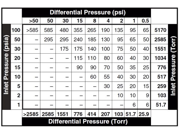 Figure 1 - Index Number Table
Locate the Index Number – where your selected row and column intersect. - If you are using N2, skip to step #3. For other gases, calculate the Density Correction Factor (DCF) with this formula:
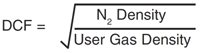
Multiply this Density Correction Factor times the Index Number found in step 3, to determine your density-corrected Index Number. - Go to the Orifice Selection Graph (Figure 2) and locate your Index Number along the bottom axis.
Draw a vertical line at your Index Number. This line will intersect with the Max. Flow Rate lines for available valve orifices. Choose the orifice whose maximum flow rate exceeds your requirements.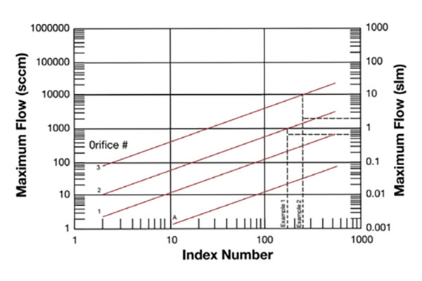 Figure 2 - Orifice Selection Graph
Example 1:
You want to control your process pressure at 5 psia, with a flow rate of 750 sccm of N2. Your inlet pressure is 15 psig (30 psia), giving a differential pressure (delta P) of 25 psi. Your delta P of 25 psi gives an Index Number value of 175. Drawing a vertical line on the Orifice Selection Chart at 175 indicates that Orifice #2 would be the best choice.
Example 2:
You want to control a vacuum process at a pressure of 0.5 psia, with a flow rate of 2000 sccm of He. Your inlet pressure is 15 psia, giving a differential pressure (delta P) of 15 psi, resulting in an uncorrected Index Number value of 90. The gas density correction for He is calculated as

Multiplying 2.6 by 90 gives a density-corrected Index Number of 234. Drawing a vertical line on the Orifice Selection Chart at 234 indicates Orifice #3 would be the best choice.
This information subject to change without notice.
Learn more about 649B Downstream Pressure Controllers with Mass Flow Meter here