Baratron® Capacitance Manometers
"Baratron® Basics"
Introduction
Baratron® capacitance manometers are usually stand-alone transducers typically requiring a ±15 volt power supply and deliver a 0-10 volt pressure signal that is directly proportional to pressure.
Baratron capacitance manometers measure true pressure (defined as force/unit area). This means that the measurement is insensitive to the type of gas being measured. Other gauges, such as Pirani, thermocouple and ion gauges, do not measure true pressure and therefore their readings will be gas-type sensitive.
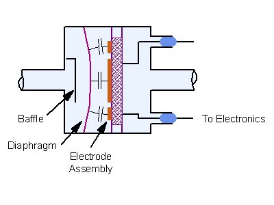
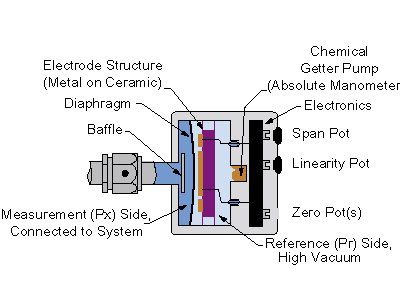
The Sensor Capsule
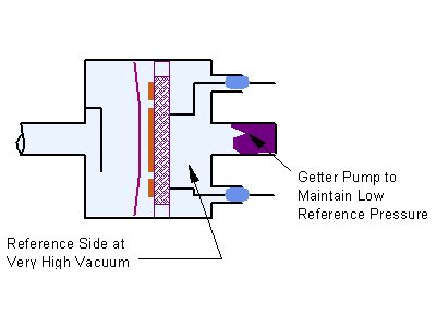
The sensor capsule contains the diaphragm and the metal-on-ceramic electrode structure. The reference side (backside) of the diaphragm is evacuated to a very high vacuum, much lower than the pressures that are to be measured. The high vacuum on the reference side is maintained over the life of the manometer by means of an internal chemical getter pump. The sensors are made of Inconel all-welded construction for ruggedness and compatibility with process environments.
Pressure is determined by measuring the change in capacitance between the metal diaphragm and an adjacent, fixed dual electrode. The radially tensioned diaphragm provides very low hysteresis, excellent repeatability, remarkably high resolution (1x10⁻⁵ of Full Scale), fast response, and the ability to measure extremely low pressures.
If a high overpressure is applied to the manometer, the diaphragm will bottom out on the electrode substrate, preventing permanent damage to the sensor. Most MKS Baratron capacitance manometers have an overpressure rating of 45 psia or 2-times the Full Scale range, whichever is greater. Pressures of greater than the allowable rating can cause internal mechanical failure or significant changes in the zero.
Electronics
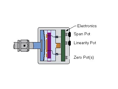
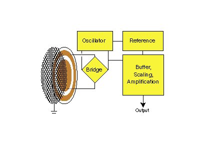
The electronics are located adjacent to the sensor. The signal conditioning circuitry is very stable and produces a high level output. The electronics consist of a precision sine-wave oscillator that drives the bridge circuit. An imbalance in the sensor electrode capacitance produces a difference output that is amplified by the buffer. The offset, gain and linearity of the output are adjusted by the zero, span and linearity potentiometers.
Adjustment pots are provided for zero, span and linearity. The span and linearity pots are covered and should only be adjusted by trained operators when performing a calibration where the transducer can be compared to a reference standard.
Zeroing
Baratron capacitance manometers are precision electromechanical devices. Like all such tightly toleranced devices, temperature and other environmental factors will have an effect on performance. In the case of the capacitance manometer, the electrical output at zero pressure is subject to changes due to shipping and handling. For this reason, all capacitance manometers require zeroing upon installation and the zero should be monitored on a routine basis.
Before zeroing, ensure that your Baratron capacitance manometer has been warmed up for the required period of time.
| Adequate Warm Up Time? | |
|---|---|
| Non-Temperature Regulated, all Ranges: | 15 minutes |
| Temperature Regulated, 1 Torr & Above: | 4 hours |
| Temperature Regulated, Below 1 Torr: | 8 hours |
Note: Times are worst case and may vary with model
Zeroing simply requires that a sufficiently low pressure be applied to the inlet (Px) side and then the electronics are adjusted accordingly for a zero volts output. This condition is achieved when the inlet pressure is below the resolution of the instrument. This maximum pressure for zeroing will be different for each range of manometer. Any pressure below the maximum is, of course, acceptable. Since gravity influences the position of the diaphragm, zeroing must be done in the same orientation in which the Baratron capacitance manometer will be used. Span and linearity are not position sensitive.
Zero, Span & Linear Adjustments
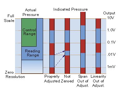
When a capacitance manometer's electronics are properly adjusted, there will be a direct correspondence between pressure input and voltage output (see chart below).
- If the zero is misadjusted, an offset will be induced across the entire range of the instrument.
- If the span is out of adjustment, the overall range will be greater or smaller than it should be.
- If the linearity is out of adjustment, the endpoints (zero and Full Scale) may be correct, but the intermediate readings may be in error.
Span and linearity are factory adjusted and are stable over long periods. These adjustments should not be touched unless suitable calibration equipment and trained operators are available. Zeroing should be done upon installation and should be checked on a regular basis. The frequency will primarily depend upon environmental conditions such as changes in ambient temperature or physical orientation of the instrument.
Scaling
A typical capacitance manometer's signal conditioning electronics will provide an output varying from 0 to 10 volts with a linear relationship between output voltage and pressure. As shown below, capacitance manometers are described by their Full Scale pressure, that is, the pressure corresponding to 10 volts.
| 1000 Torr Full Scale | 1 Torr Full Scale | ||
|---|---|---|---|
| 10 V | 1000 T | 10 V | 1 T |
| 1 V | 100 T | 1 V | 0.1 T |
| 0.1 V | 10 T | 0.1 V | 0.01 T |
From this it is apparent that, at pressures significantly below the Full Scale pressure, the output voltage will fall to very low values. As a consequence of this, there is a resolution limit which is typically 1 part in 100,000. Thus the resolution of a 1000 Torr Full Scale manometer is 0.01 Torr, corresponding to an output of 0.1 mV.
Between the Baratron capacitance manometer's Full Scale rating and its resolution, we define two pressure ranges over which the manometer will provide a useful (accurate and repeatable) output:
- A Reading Range typically of 3.5 to 4 decades (depending on the model) where the manometer is used for measurement (see chart)
- A Control Range typically of 2.5 decades (depending on the model) when the manometer is used in a pressure control system with 50 mV minimum into the control system. This narrower range helps to assure immunity from system noise.
Accuracy Terminology
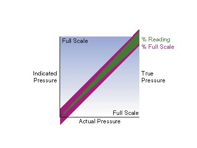
MKS capacitance manometer technology expresses accuracy as a percent of Reading, not Full Scale (as is the case with some lower performance devices from other manufacturers). For example, the Type 622A instrument has a specified accuracy of 0.25% of Reading. For a 100 Torr Full Scale manometer, that means the error could be up to 0.25 Torr at 100 Torr, down to 0.025 Torr at 10 Torr, etc. In other words, the absolute value of the error declines through the measurement range. So percent of Reading accuracy ensures that your measurement is as precise at 10% of Full Scale as it is at 100% of Full Scale.
For a competing 100 Torr instrument with a 0.25% of Full Scale accuracy, the error would be up to 0.25 Torr at any Reading pressure. In this case, the error at the low end of the measurement range has increased uncertainty as a percent of Reading. Error as a percent of Reading versus Full Scale is represented in the graph below. The green line represents the inaccuracy as a percent of Reading and the additional inaccuracy of percent of Full Scale instrument is indicated in pink. Accuracy defined as a percent of Reading provides you with a more accurate output signal in the lower scale of the pressure range than a percent of Full Scale device.
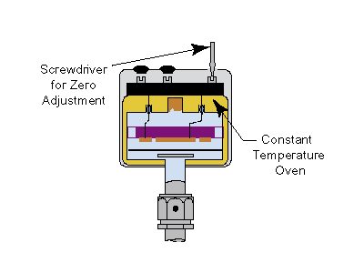
Temperature Regulated & High Temperature Baratrons
Variations in ambient temperature can result in a change in zero that is most noticeable in the lower end of the instrument's range. This effect may be minimized by using a temperature regulated Baratron capacitance manometer. By incorporating a well-regulated oven (usually at 45°C) within the transducer, a significant improvement in stability can be achieved.
Higher temperature Baratron capacitance manometers (100, 125, 150 & 200°C) can be used where it is also desirable to minimize the accumulation of condensable by-products in the manometer. Such by-products are produced by some Etch and CVD processes. The effect of condensables accumulating on the diaphragm is a continuously shifting zero. Eventually, enough material will accumulate and it will no longer be possible to zero the instrument.
Installation
Do:
- Make a proper vacuum connection to the system. If using a VCR fitting, use a new gasket, hand tighten and, using a wrench, tighten according to the manufacturer's recommendation. Do not over-tighten.
- Allow adequate warm up time.
Don't:
- Twist units (twisting may cause internal damage resulting in performance problems).
- Bang or drop the unit.
- Make any adjustments to the span or linearity pots as this will change the calibration.
- Install a low Full Scale unit (0.1 Torr and below) in any orientation other than the calibrated orientation.
Zeroing Procedure Preparation
Allow adequate warm up time noting the varying requirements for non-temperature regulated, heated and low range transducers. If using a breakout connector, install the connector before the warm up.
Ensure that the manometer is under vacuum and the pressure is at or below the maximum zeroing pressure when actually making the zero adjustment (below).
Proper Zeroing Pressure?
0.1 Torr <1 x 10⁻⁶ Torr
1.0 Torr <1 x 10⁻⁵ Torr
10.0 Torr <1 x 10⁻⁴ Torr
100.0 Torr <1 x 10⁻³ Torr
1000.0 Torr <1 x 10⁻² Torr
An MKS Baratron capacitance manometer may be zeroed using a power supply/display unit, a Digital Volt Meter and breakout connector, or from the process tool's controller.
It is a good idea to log zero data to capture long-term performance of each unit.
Zeroing with the Baratron Capacitance Manometer Connected to a Power Supply/Display Unit
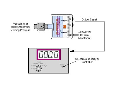
The Baratron capacitance manometer may be zeroed using the zero adjustment pot on the display unit (preferred) or by using the zero pot on the manometer. If using the zero pot on the manometer, set the zero pot on the display to mid-position. Adjust the zero pot with a small screwdriver until the display reads 0.000 volts.
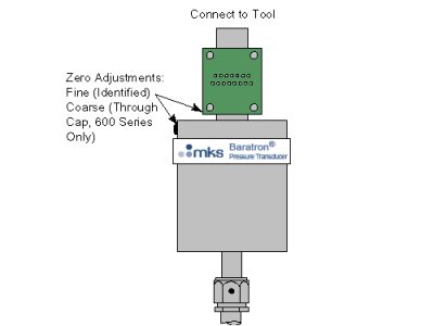
600 Series Baratron capacitance manometers have a coarse zero switch that is located on the side of the instrument. If there is insufficient adjustment range with the zero pot, turn the pot to mid-position and adjust the coarse switch to the position that produces an output signal closest to zero volts. Then adjust the zero pot on the top of the unit until the voltage is exactly zero volts.
Zeroing with a Breakout Connector
Follow the same procedure as above using the zero pot on the manometer. The signal voltage will be measured with a Digital Volt Meter connected to breakout connector pins 2 and 12 instead of from the display unit.
Zeroing from the Process Tool's Controller
The procedure is essentially the same as zeroing from a power supply/ display unit. However, the controllers of most tools do not recognize negative voltages. To ensure that the zero does not have a negative offset, adjust the zero to about 2 mV positive.
Periodically check to ensure that the zero setting remains slightly positive. For additional installation detail, see product manual.
General Troubleshooting Guidelines
Improper operation of your Baratron Capacitance Manometer may often be traced to factors such as:
- Inadequate warm-up time as indicated by drifting of the output pressure signal or zero adjustment.
- Improper zeroing as indicated by non-repeatability of a pressure measurement.
- Power supply voltages either not present or noisy as indicated by no output pressure signal or an erratic output.
Check Your Installation
- Does your Baratron capacitance manometer show signs of physical damage?
- Has the Baratron capacitance manometer been properly connected, physically and electrically?
- Have you allowed adequate warm-up time?
If the warm-up has not been long enough, the internal components of the Baratron capacitance manometer will not reach thermal equilibrium and the readings will drift. - Has the Baratron capacitance manometer been properly zeroed?
If not, the pressure indications will show an offset. - Are you aware of any tampering with the span or linearity adjustments?
If so, the instrument's calibration will be off. Call your local MKS Service Center.
If none of the above appears to be the problem, a simple series of electrical checks will often locate the problem.
Electrical Troubleshooting
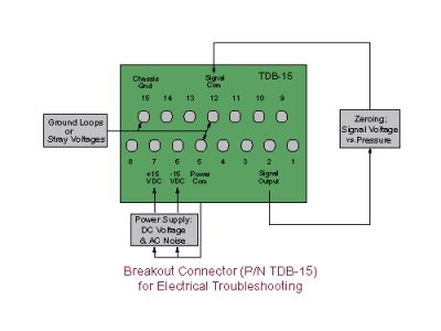
Install a breakout connector as shown in the illustration.
Use a Digital Volt Meter (DVM) with at least 4.5 digits.
- With the DVM set to measure DC voltage, check the power connections (usually ±15 volts).
- With the DVM set to measure AC voltage, ensure that the AC noise is less than 50 mV RMS on the plus and minus power connections.
- With the DVM set to measure DC voltage, check for ground loops or stray voltages between the common and ground pins. No voltage should be present between any pair.
- With the DVM set to measure DC voltage, the output pin should measure between 0 and 10 VDC, proportional to pressure and depending upon the Full Scale pressure rating of the manometer. For example, a 1 Torr Full Scale manometer will create a 1 volt change for every 100 milliTorr change in pressure.
- Check to ensure that the pressure as measured at the unit's pin corresponds to the pressure that is displayed on the screen of the controller. If not, there is a problem with the pressure to voltage (A/D) conversion. Check the A/D calibration and make sure you are using the correct range transducer.
- At or below the maximum zero adjustment pressure, the output signal pin should read 0.000 volts. If not, adjust the zero pot as described in the zeroing procedure.